 |
|
 |
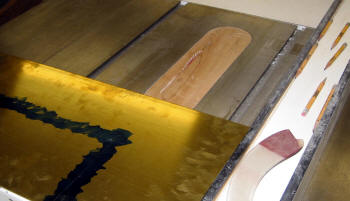
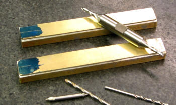
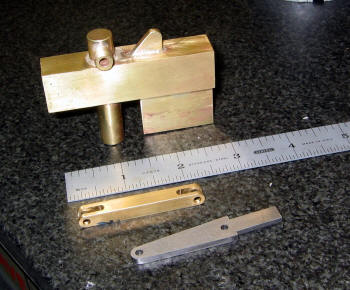
My neighbor made the former and backing
plate for me. Checked the dimensions with the surface plate and
gauge ... perfect! The Copper sheet is .04" and the 260 Brass 3/32"
is for the floor.
|
|
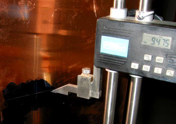
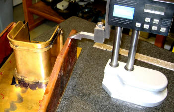
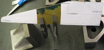
The height gauge is sitting on a
pair of V blocks which measured 4.905". Now cutting the copper
sheet to the required dimensions was easy. I used my bench sander
to smooth the edges and make the radius.
|
 |
|
 |
Same
neighbor has a table saw with a carbide blade ... cut through the
Brass plate very easily and was amazingly square. Then I used his 4
foot edge sander to smooth out the edges and the basic floor plate
was done ... ready to drill all the holes. But I am going to drill
selective holes ... I want everything to line up correctly!
|
|
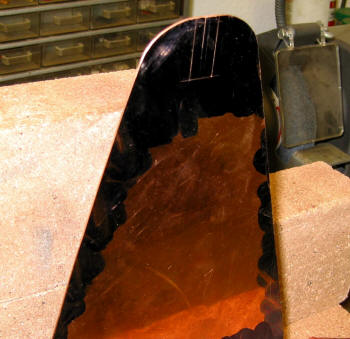
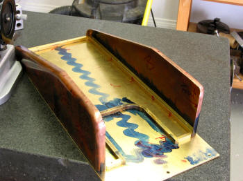
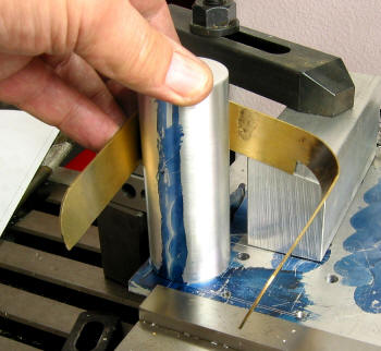
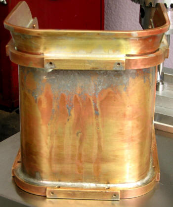
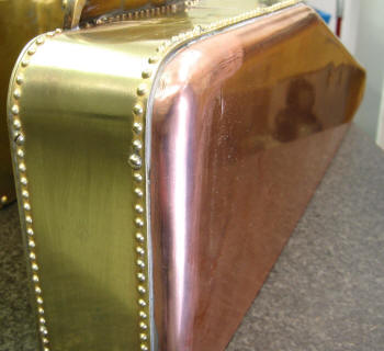
The copper side plate is ready to be annealed, it looks
funny here but it is actually symmetrical.
|
 |
|
 |
|
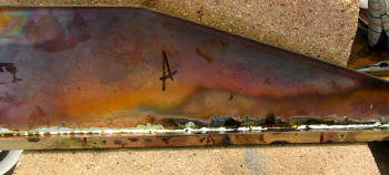
Annealed and I have started to form it ... this turned out to be a
lot easier than I thought. Just lightly hammered the edges using my
bright orange soft plastic hammer. |
|
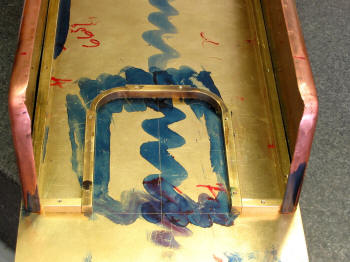
This picture really shows what
not to do ... I should have
started closer to the rounded edge then hammer the straight edge.
It worked out okay as you will see later. I annealed the straight
edges twice and corners 3 times before I was finished. |
 |
|
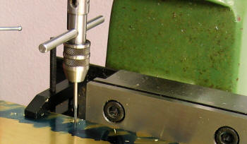 |
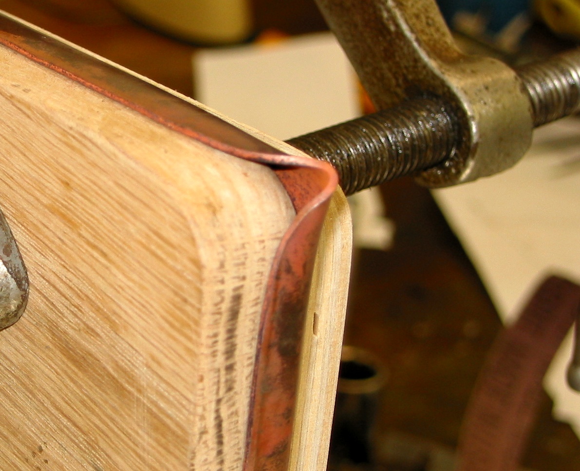
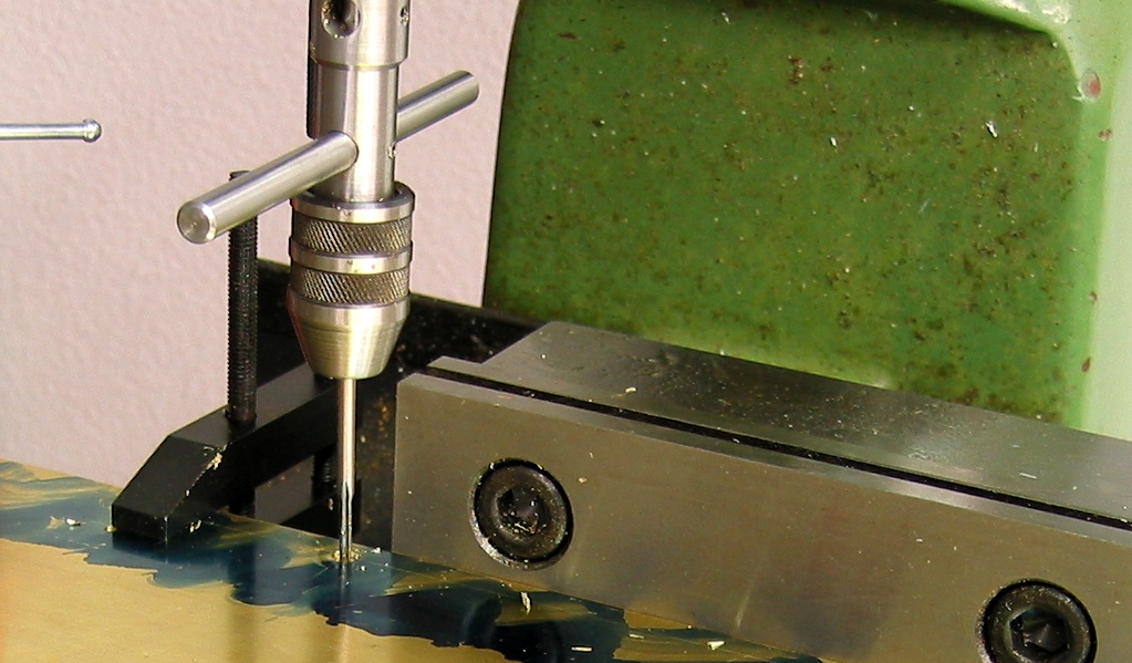
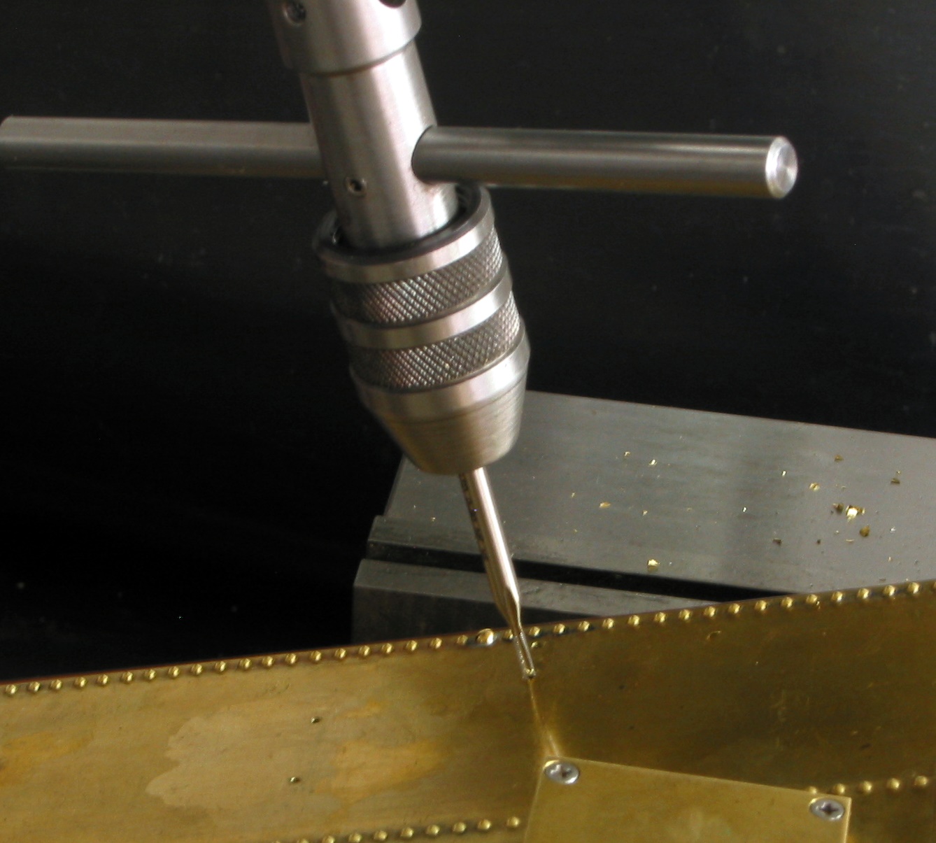
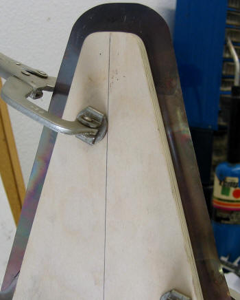
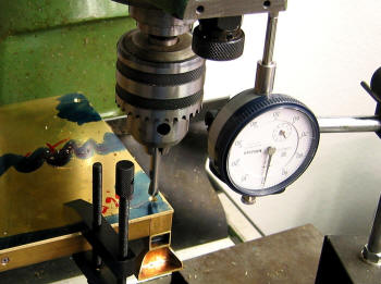
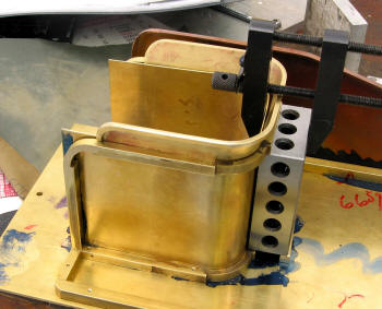
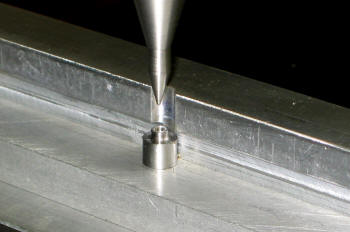
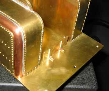
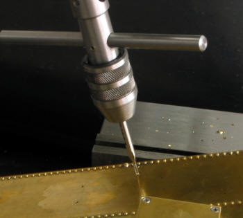
| To ensure a
perfect fit I attached the floor to the frame then center drill,
counter sink, drill and tap without removing the assembly. Each
hole was done the same way. |
|
Nice to have a vice that will clamp the whole frame. |
 |
|
 |
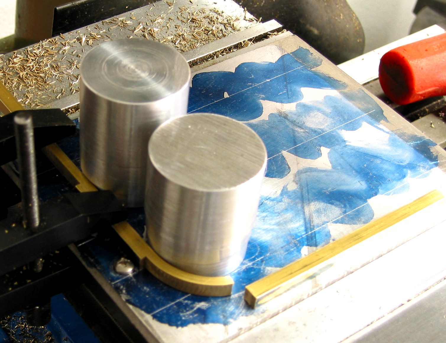
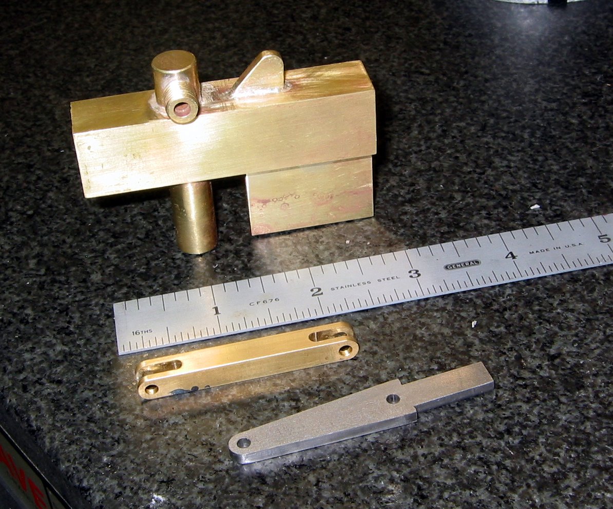
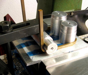
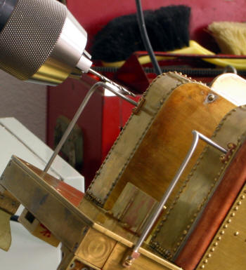
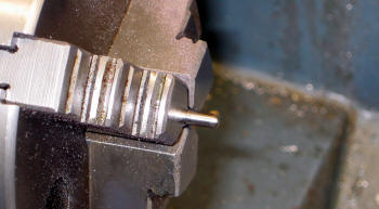
This is my fixture that I used to bend
the horseshoe braces ... multiple uses! Just change the aluminum
cylinders and I had a different radius. This bending was done
without annealing the Brass rod. As you can see it snapped. I
emailed Robert to find out if this was normal. Yep ... annealing
required.
|
|
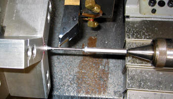
Tried again ... this time I had
annealed the Brass to a dull red ... bending was so much easier. I
annealed it again to reduce some of the spring back ... I think it
helped a little. Those two screws prevent the bar from bowing out
... keeps it straight.
|
 |
|
 |
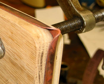
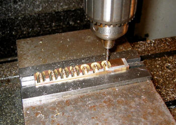
Each and
every counter sink hole was done with the mating part attached,
that way all mounting screws were located exactly in the correct
spot for re-assembly. Took more time, but was well worth the
effort.
|
|
Closer view of the bottom horseshoe. |
 |
|
 |
Top Horseshoe getting the second bend ... same fixture just
different attachments. Be careful on this radius ... Kozo provides
the outside radius ... here I needed the inside radius. Makes a big
difference when trying to get everything fitted.
|
|
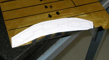
This is the template that Robert
sent me for the Verge Board... glued to the brass sheet. Just cut
it with band saw and formed the curves with the table belt sander.
|
 |
|
 |
|
This arrangement provides the correct position to obtain the 15
degree tilt for the Verge Board. The block of Aluminum has a cutout
with about a 11.6 degree slant. We want the corners to be vertical
at the center of the bend. |
|
I again used the bending tooling
for the Vertical Board only with much taller columns. I thought
about trying using Kozo's method using sandwich plates for bending
... just didn't think I could do it ... so I used my fixture
method. The next step is to assemble the parts using 1-72 screws.
Here I'm making sure everything fits just right before I start
drilling holes!
|
| Update
9/12/07 |
Well it
has been a long time since my last update (5 months, where does the
time go?!). A lot has been done ... it's just that some of the work
is very detailed and takes a lot of time. Plus I acquired some new
equipment and that took away from the A3 project. Also I took a
Welding course at the local college ... to expend my capabilities.
|
 |
|
 |
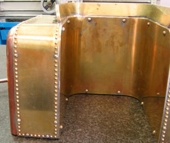
Above I am taking some last measurements before I start soft
soldering the side plates. As you can see the Coal Bunker has been
assembled and secured with 1-72 screws. So it is also ready for
soft soldering.
|
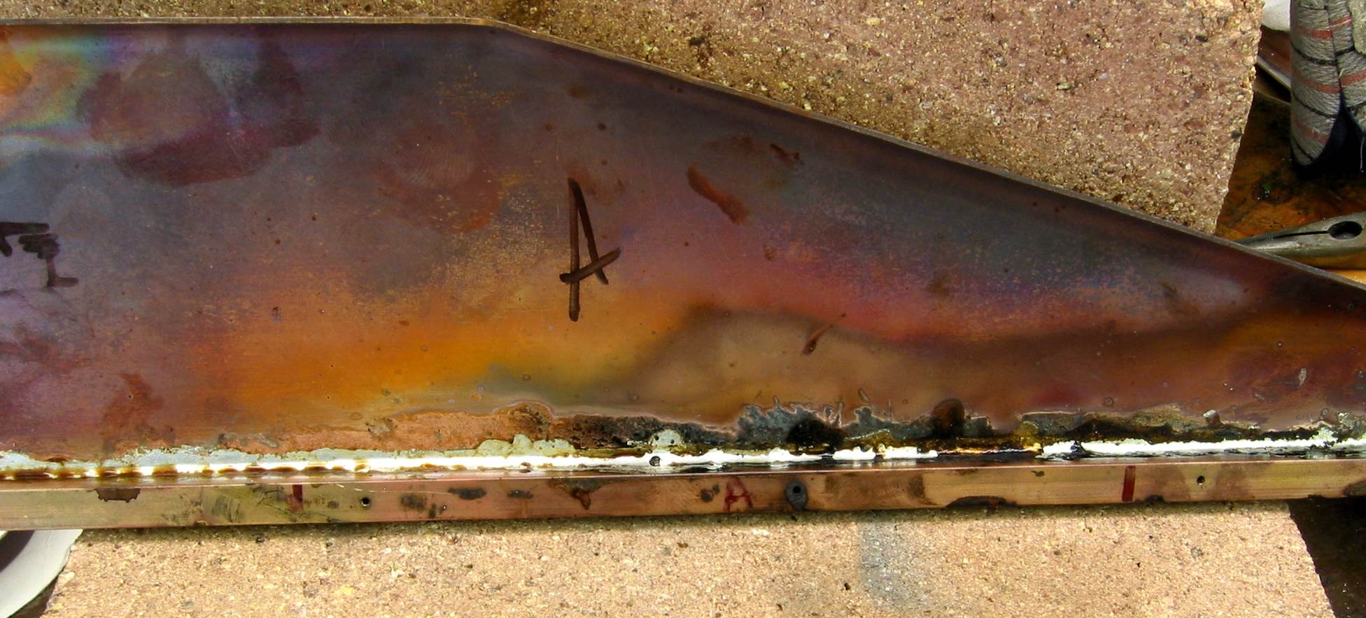
|
Side panels soft soldering ...
completed. Looks messy and has too much solder. I used Oatey Solder
and H-2095 Water Soluble Flux so it is easy to clean. The only
problem with this solder is that it has a diameter of 1/8". I have
to get better at soldering before I start on the Top Plate.
|
 |
|
 |
More soft soldering ... think
I am getting better!
|
|
And better! Look at the bottom not the top! |
 |
|
 |
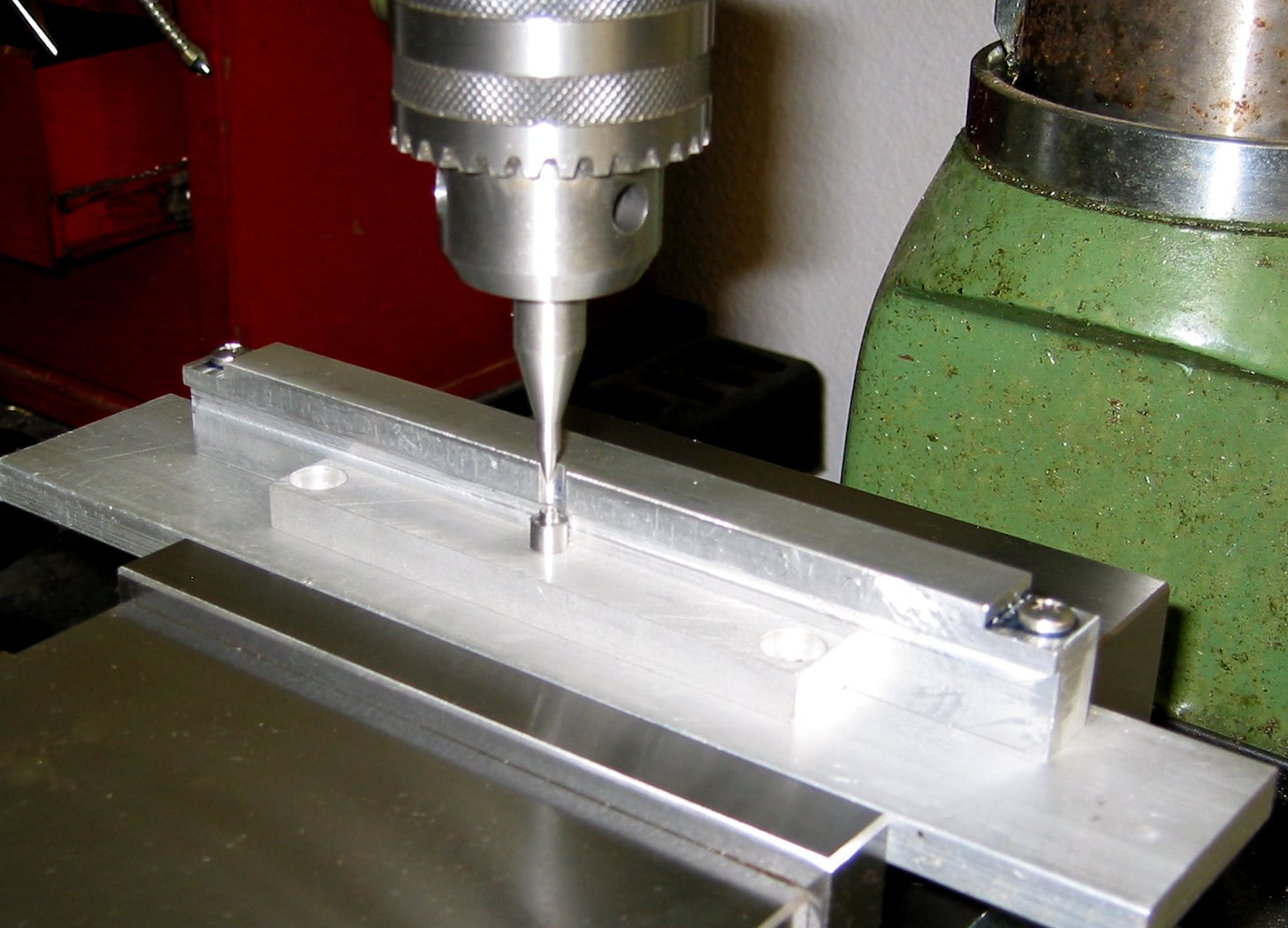
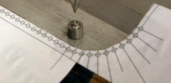
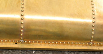
This is my embossing set up. The back guide is used to keep the
panel straight and set the distance from the rivet head to the
panel edge at .078" or 5/64" consistently for each and every rivet.
|
|
A closer look ... I tried to set the diameter of the die to
equal the spacing, but couldn't. So I ended up using the surface
plate and height gauge to scribe the location of each rivet ...
time consuming but it worked great. My spacing ended up at .1325".
I used this number so I would not end up have cutoff rivets at the
corners.
|
 |
|
 |
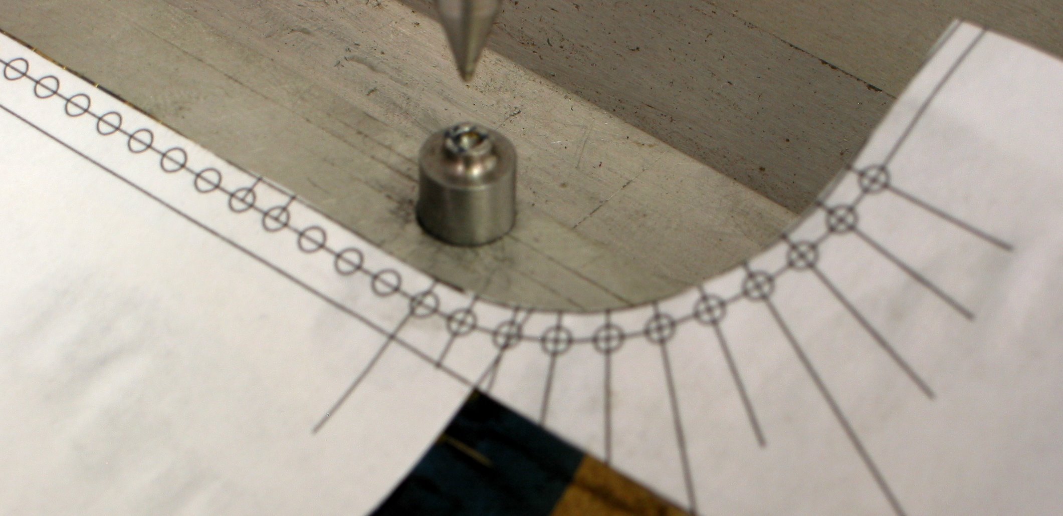
For the curves I made a drawing and pasted it on the Top Plate ...
no back guide here. I also set the depth of the die so that the
rivet height is about .025". I got that from Kozo's Building the
New Shay.
|
|
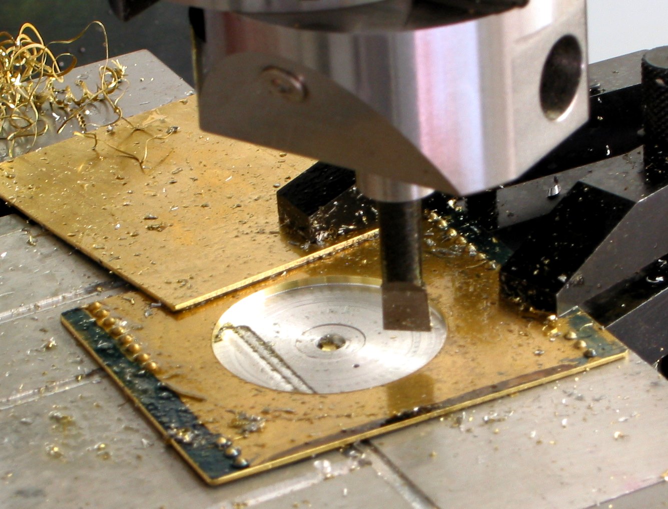
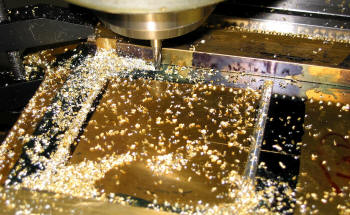
Finished embossing for now ... here cutting out the
rectangular hole for the manhole assembly.
|
 |
|
 |
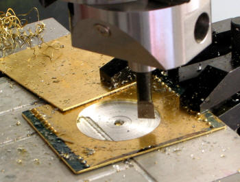
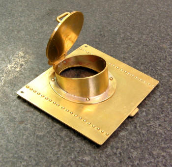
The mounting flange for the manhole ... came from the Top Plate
cutout. See below for fitting ...
|
|
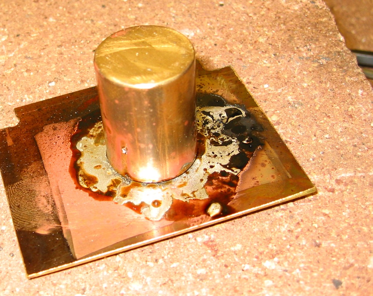
The beginning of the manhole cover ... a suggestion ...
pre-solder the plate and then the cylinder. Then heat together ...
it works much better than trying to heat the whole thing! |
 |
|
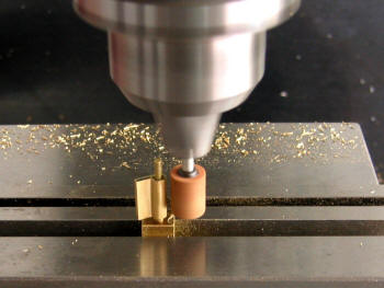 |
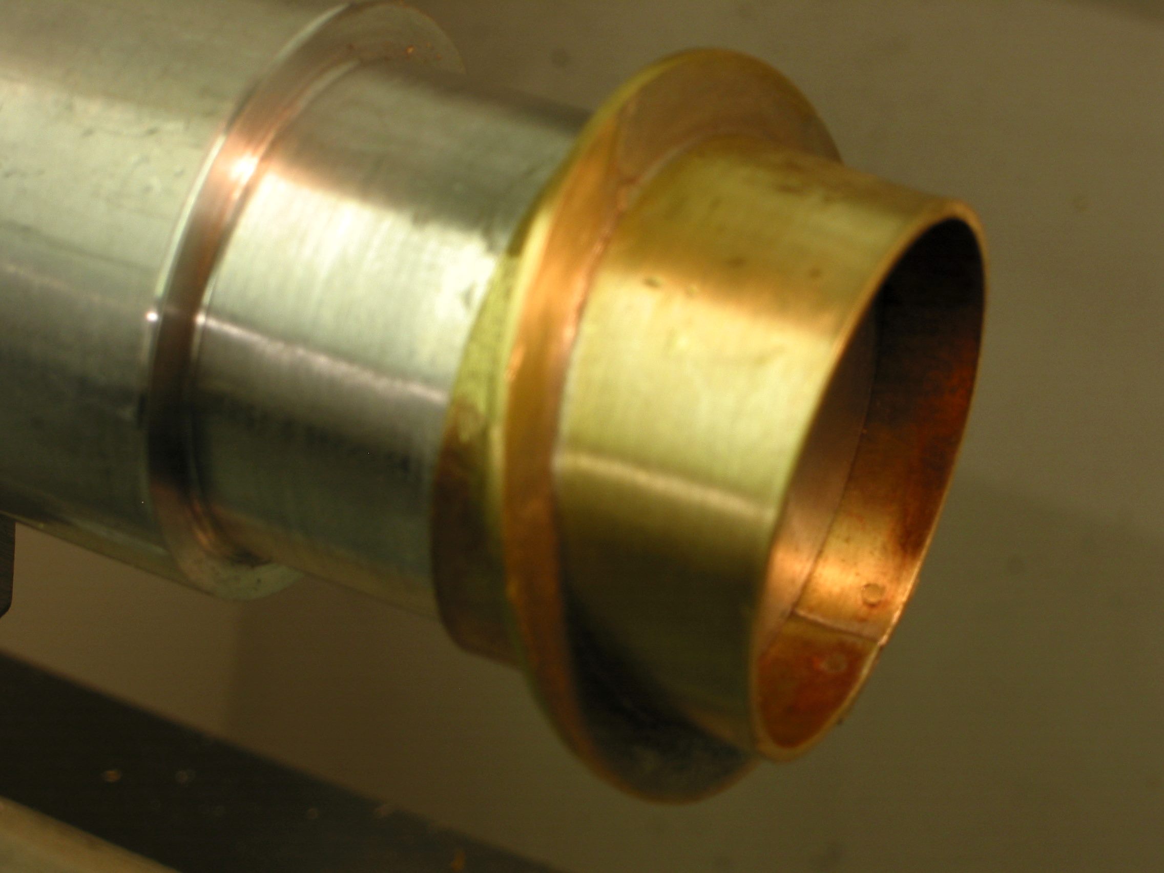
I could not get the manhole assemble on the 9x20 chuck to cut the
flange to size. So I used a mandrel instead, also used it as a
former to get the tube inside diameter the correct size.
|
|
Here is one of those little hinges ... the radius must be
very close to .078" (5/64") otherwise the door won't open/close all
the way. |
 |
|
 |
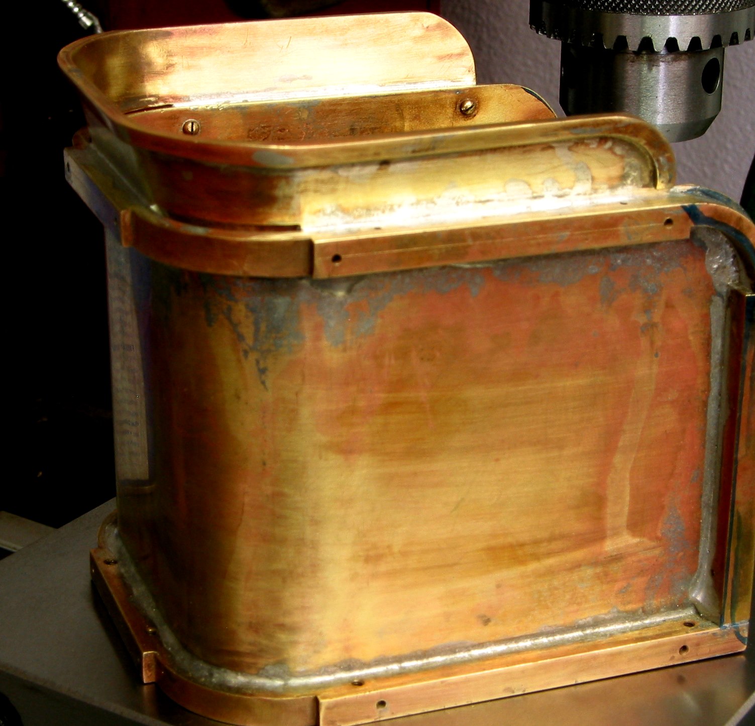
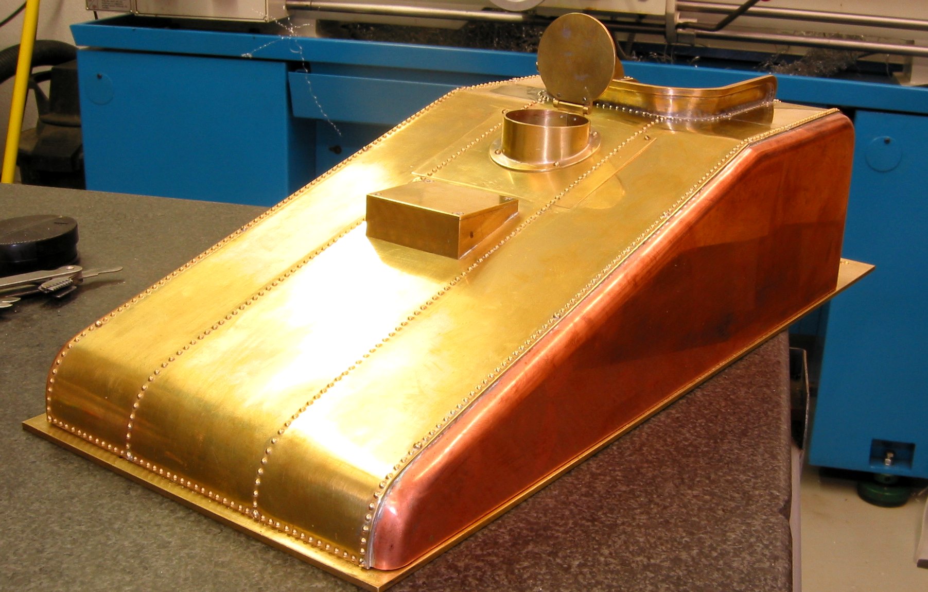
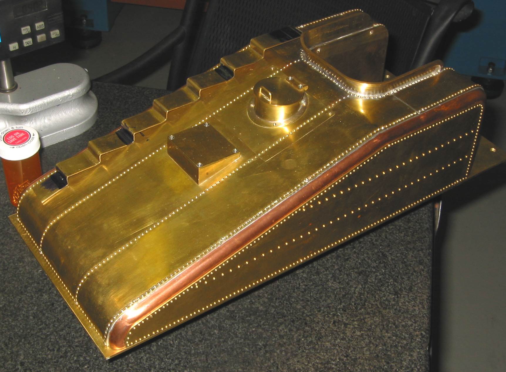
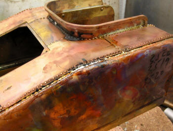
Well I put the soldering off as long as I could ... in spite of its
looks, I am very please with the results. I was able to control the
amount of solder so that it did not overflow too much on the top
surface.
|
|
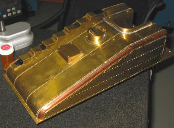
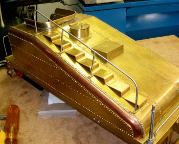
The Tender Tank really cleaned up nice! |
 |
|
 |
|
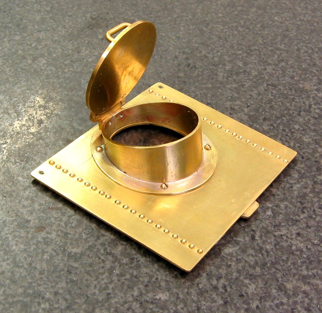
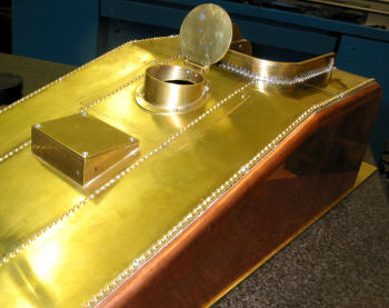
The finished Manhole assembly. Notice the rivets ... Kozo does not
show them on the drawing for the plate. But they are shown in the
various pictures. I like the looks as it maintains a continuity on
the Top plate. |
|
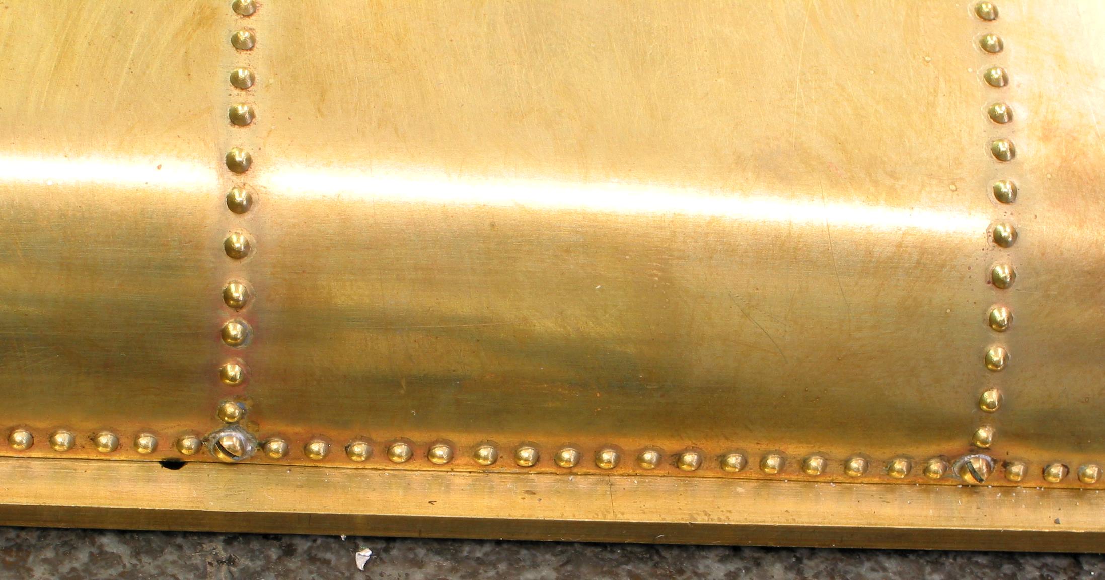
Close up of the Coal Bunker. |
 |
|
 |
Notice that solder came through just a little on the mounting
screws. By the way ... that little hole in the bottom plate ... an
earlier mistake. Later on I will fill the hole so that no one will
ever know it was there!
|
|
Almost done!
What is that in the background?
|
 |
|
Still have lots to do on the tender...
Dummy Side Plates
Coal Stopper
Steps
Handrails and Handholds
Then I can move on to the Hand Pump and the Piping...
|
That copper and brass really shines nice.
|
|
|
Although
I still have lots to do on the Tender Tank I am looking ahead to
the Driver Wheels. In fact, I'm taking a Fabrication class at the
local College. There I will get some additional experience in the
machine area and CNC. I hope to make the Driver Wheels using CNC. I
have some machinable wax and 12" of 12L14. The big thing is they
have a Haas VF 1, 2, 3 and a new VF 4.
This ought to be fun!!
Until next time ....
|
| Update
12/10/2007 |
Since my
last update I've spent most of my time has been writing the G code
for the Drivers. I had a opportunity to use a Haas CNC machine at a
local college so I jumped ahead. So here are a few pictures showing
what was done on the Tender Tank: Dummy Side Plates, Coal Stopper
and Handholds.
|
 |
|
 |
|
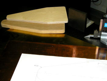
I used a print out from the Cad program to correctly size the Dummy
Side panels. There are actually two panels sandwiched together so
that the dimensions and curves will be the same for both sides. |
|
Not much to see here ... just
the Coal Stopper and part of the Dummy Side panel. I wonder if the
Coal Stopper is high enough, maybe I will go back a make it higher
when in actual use.
|
 |
|
 |
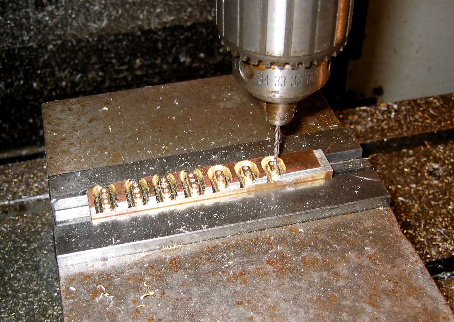
Pictured above is a 1/16" strip of sheet brass soft soldered to a
brass bar . The line in the blue layout ink is to locate the Y
coordinate on the CNC machine. These will be placed in a vice and
machined using the Haas CNC.
|
|
Just finishing the last Handrail
Support ... total 8 pieces of the 3 hole and 6 of the 2 hole. Took
all of 5 minutes to run ... won't say how long it took write the
program ... but it was my first hand written program ... no CAM
software. Just straight G code.
|
 |
|
Still have a little more work on the Tender:
Handrails to bend and mount.
Machine the Handholds .... wonder if I can use the CNC lathe they
have ... that would be nice as I need four of them!
Mount the Steps.
The Hand Pump and Tender Piping\. |
A better view of the Dummy Side panel, the embossing was the same
shown before just a lot more ... glad I'm done with that for now.
The Steps still need to be finished and then mounted.
|
|
|
| Update
May 24, 2008 |
Time does
fly when you are having fun!! This update covers the remaining
build for the Tender, except for the Headlight and Painting. These
things will be done when the Engine completed (a
few years from now!). There are a few minor items that I may
change ... I will point out these later.
Note that all photos are thumbnails ...
click on them to enlarge then "Back arrow" to continue.
|
 |
|
 |
|
The handrails and stairs were not all that difficult to make ...
mounting them on the Tender was a bit more difficult. The hole
placement has to be just right. |
|
This seems a little extreme ...
but it did work! I didn't want to tilt the head too much so I
adjusted Tender some. I found out later that a friend had a right
angle attachment. With that I would not have to re-tram the head.
|
 |
|
 |
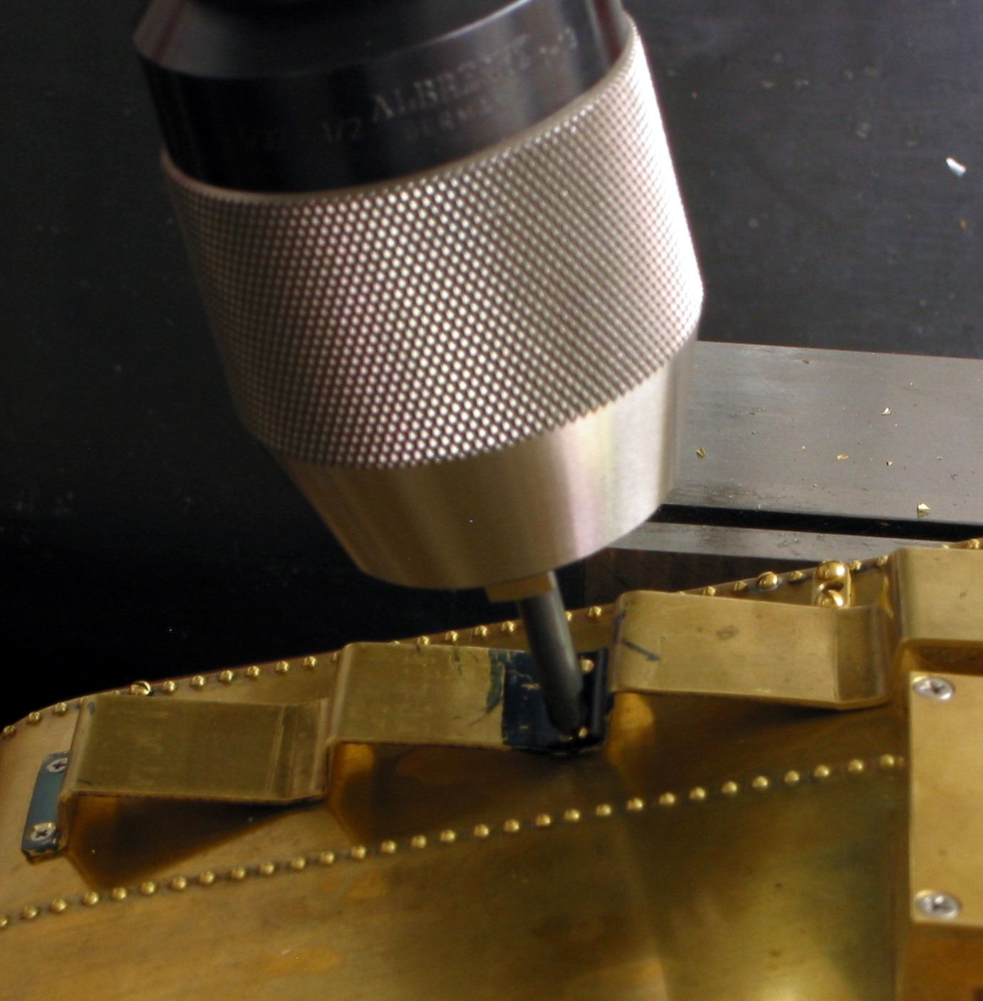
Same idea, but for the Stairs and Handrails not so much of a tilt.
Once I got the 1st screw in place I would drill the counter sink,
then the hole for the tap, move the Y axis over 0.531" and repeat
for the next mounting screw. Remove Stairs then tap, move back and
tap that hole.
|
|
This tap is for the Handrails pads. Used the same sequence
as I used for the Stairs.
|
 |
|
 |
|
Keeping things straight. |
|
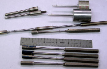
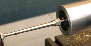
This is one of the Handholds
that was machined on the Haas CNC Lathe. Although the program was
simple and short ... the setup was not. After many trials (see next
photo) I found that I had to use the tailstock to support the long
thin hex rod. The extra material was needed because the tool had a
be a certain distance away from the tailstock. |
 |
|
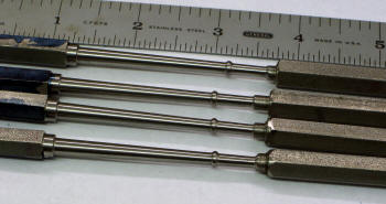 |
Sample of the trail and error results along with the almost
finished Handholds. As expected ... all four came out the same.
|
|
A close up ... not all of the machining was done on this
CNC. After this I took them home to finish them. |
 |
|
 |
|
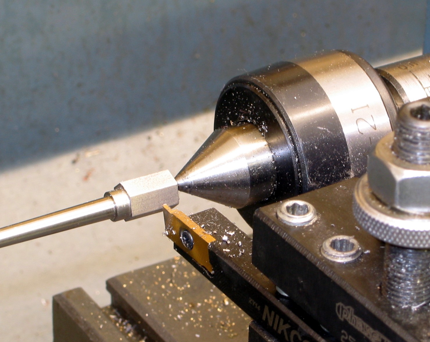
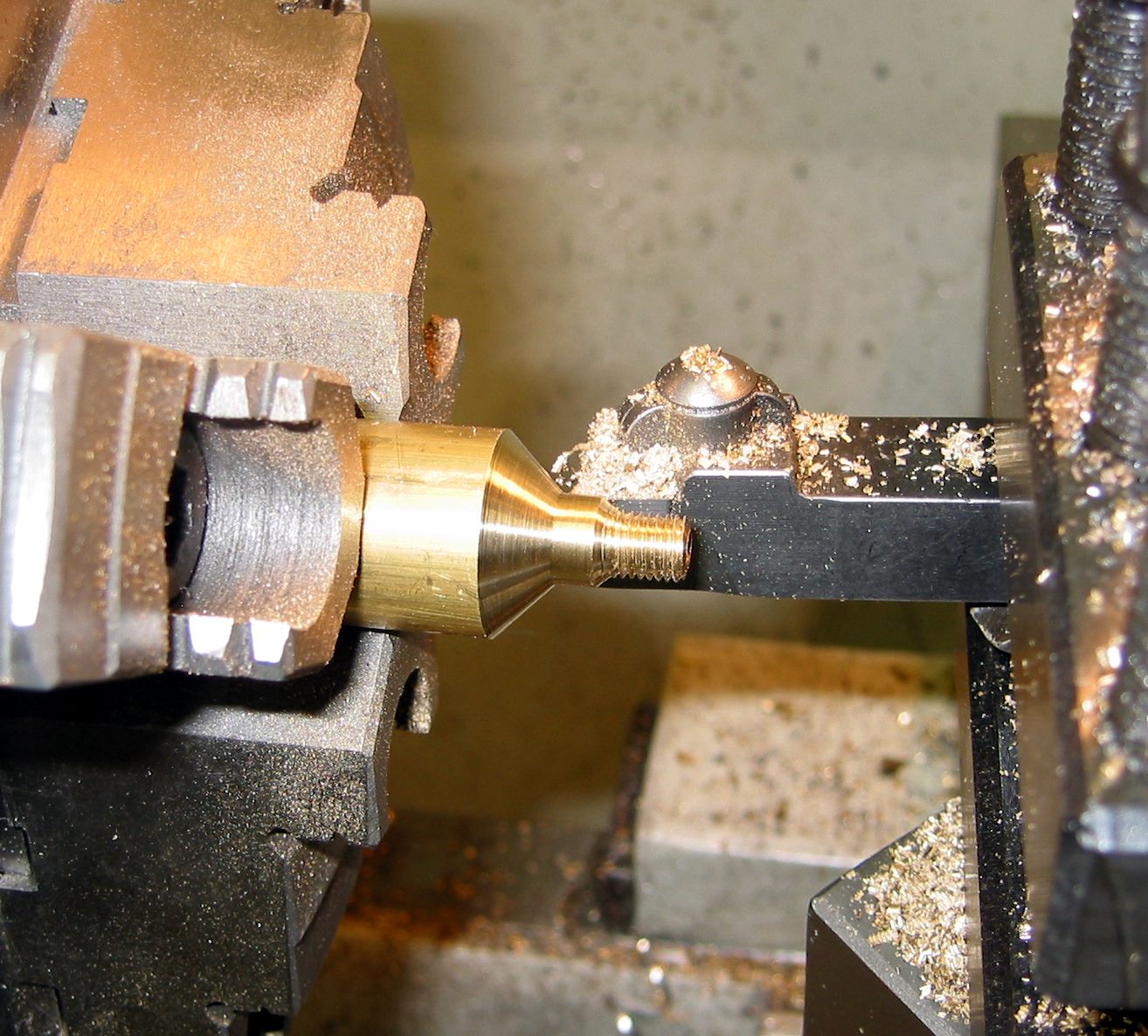
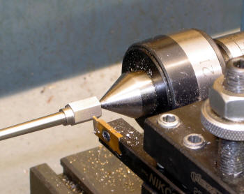
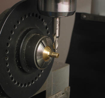
Getting ready to turn the diameter for the threads. Here I'm
setting the tool for the correct position. Once that is established
I changed to the other cutting tool. |
|
Simple enough ... |
 |
|
 |
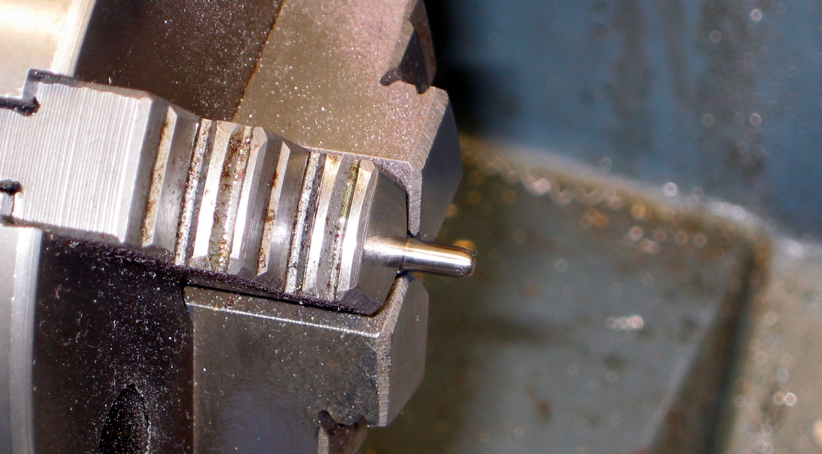
And finally the rounding tip ...
|
|
Putting it all together... |
 |
|
 |
|
Getting closer... |
|
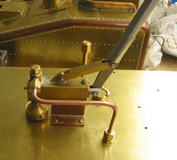
The Tender Pump along with Link
and the Lever (these were done on the CNC). I had a real hard time
with drilling the column ... had to replace it 2 times (stupid
errors). But once again I prevailed!
|
 |
|
 |
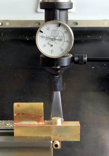
For some reason I was not able to fit the pump body in my lathe to
drill the valve top seat and the bottom hole. So I set it up on the
mill and used the co-ax indicator to find the center of the column.
|
|
I did a lot of turning on the opposite side with the lathe
in reverse. It was a lot easier to turn the taper .
|
 |
|
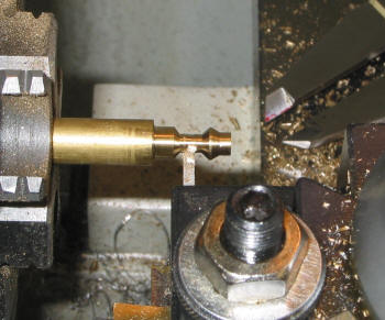 |
Turning round stock into hex.
|
|
Parting off the small parts. |
 |
|
 |
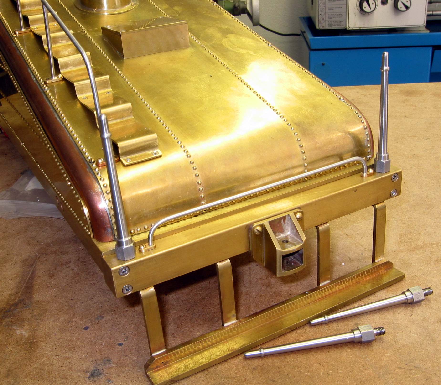
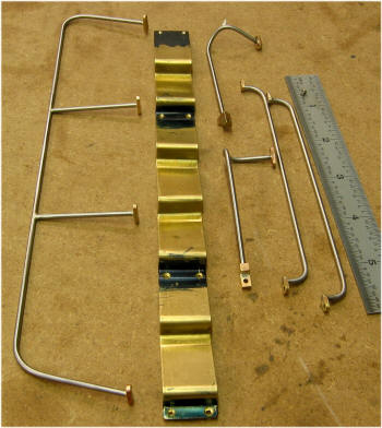
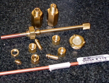
The collection of the Tender Piping. Notice I used the 5/32" tubing
from a local hobby store. The Suction Strainer ... I just could not
soft solder the brass screen. So I made it different ... not sure
that I like it just yet ... but it does work. Since I found Ed
Hume's "how to photos" I may try again.
|
|
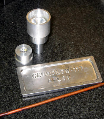
To make a right angle bend in the small tubing I filled it
with Cerrolow a metal that melts at 117 degree F. I didn't use all
of the billet ... just a small section. I also made a holding
fixture with a small hole to let the air out while filling. And a
funnel that turned out to be too big and heavy. I will slim it down
next time. I only had ONE volcano eruption.
|
 |
|
 |
The finished pump, piping and handle. Notice the suction screen is
also not soldered. The removable screen idea is actually from
Kozo's Building the New Shay as an alternate way of securing the
screen. It works for me!
The pump works pretty good, the pressure drops down from 300psi to
150 real fast then very slowly to 90. I think the spring may need
to be a bit stronger.
|
|
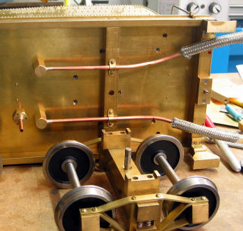
This is what the undercarriage looks like. I will finish
the brackets for the rubber tubing later when the Engine water line
are installed ... at that time I will know more of what is needed.
|
 |
|
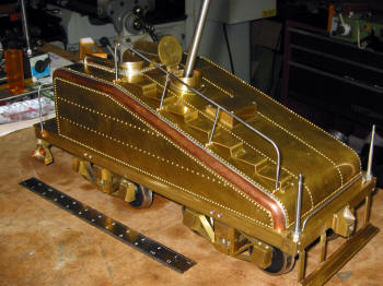 |
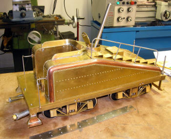
It's
finally done, well almost. I'm very happy with it ... only a few
things I might re-due.
Soon I will be ordering parts for the frame, finishing the drivers
etc.
Hope you have enjoyed the journey.
|